MARINESURPLUS.COM
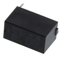
Power Relay, SPST-NO, 24 VDC, 5 A, G6B Series, Through Hole, Non Latching
Description
A compact yet powerful PCB relay engineered for control, automation, and signal switching applications. With its sealed design, dependable contacts, and efficient coil drive, this relay balances performance and reliability for industrial use.
Key Specifications & Features
|
Parameter |
Specification |
|
Contact Configuration |
SPST-NO (Single Pole, Normally Open) |
|
Coil Voltage |
24 V DC |
|
Contact Rating |
8 A (resistive load) at 250 VAC / 30 VDC |
|
Maximum Switching Voltage |
Up to 380 VAC / 125 VDC |
|
Coil Resistance |
~2.88 kΩ |
|
Operate / Release Time |
Typically ≤ 10 ms |
|
Dielectric Strength |
3,000 VAC between coil and contacts |
|
Mounting / Termination |
Through-hole PCB pins |
|
Operating Temperature |
–25 °C to +70 °C |
|
Contact Material |
Silver alloy (to ensure low resistance and durability) |
|
Sealing / Enclosure |
Fully sealed housing to protect against dust and contaminants |
Benefits & Applications
-
Compact, High-Performance Design
The small footprint makes it ideal for dense PCB layouts, while the 8 A rating allows handling of many common loads such as small motors, solenoids, or lighting circuits. -
Reliable Switching & Long Life
With fast response times and a sealed enclosure, this relay offers dependable performance even in challenging or dusty environments. -
Flexible Use Across AC & DC Loads
Although rated for 8 A resistive, this relay can switch both AC (up to 250 VAC) and DC (up to 30 VDC) loads, making it versatile for various control systems. -
Industrial & Automation Ready
A great choice for control panels, machines, instrumentation, building automation, or any application requiring a solid, high-reliability relay.
Installation & Application Tips
-
PCB Layout & Clearance
Ensure your board footprint matches the Omron G6B series pin layout and provide adequate spacing especially between high-voltage traces and relay coil pins. -
Inductive Load Protection
If switching inductive loads (e.g. motors, solenoids), include a flyback diode or snubber circuit to reduce arc damage and lengthen relay life. -
Temperature & Mounting
Allow space for cooling; avoid placing the relay near heat sources. Operate within –25 °C to +70 °C for best reliability. -
Test Under Load
Always perform a test with the intended load to verify contact performance and timing before final deployment. -
Shielding & Isolation
In noisy electrical environments or where EMI is present, consider additional board guard traces or shielding to maintain signal integrity.